|
| |
|
Tuning 101 AFR
Control Center (Air Fuel Ratio) |
|
|
|
"Hydrogen Garage owns this
product and sells it from their web site." |
| |
|
|
If you want to obtain the largest mileage
gains possible from any HHO Generator, you must modify the signals from
4 sensor groups. On most automotive emissions control systems, just
doing the O2 Sensor(s) with an EFIE will not get it done. All of the
following sensor signals must be done:
-
All Oxygen Sensors (O2)
-
MAF or MAP Sensor
-
CTS or ECT Sensor
-
IAT Sensor
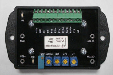
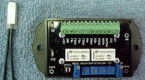
The Tuning 101 AFR
Control Center is the only device that is doing the above.
-
Thermostatically Controlled. It
activates your HHO Generator when your engine water temperature
reaches 160 degrees F. The AFR Control Center will automatically
turn on as long as your coolant temperature remains at 148 degrees
F, or higher.
-
Has Quad "True Digital" EFIE's with
Adaptive Control. Handles 4 O2 Sensors; emits a Digital signal to
the ECU.
-
Has Adaptive Control for the newer 25
MS. High Speed O2 Sensors.
-
Works with systems that have 2.5 volt
bias O2 Sensors (Chrysler, Dodge, Jeep)
-
Has 1 wire hookups for your IAT & CTS
Sensors.
-
IAT Sensor adjusted with a 20 turn
potentiometer. This adjusts your timing 1/4 degree at a time (Intake
Air Temperature). You must control Ignition Timing with a Scan Tool.
-
A Scan Gauge is
necessary for maximum mileage gains (not a Scan Tool). The
gauge is for monitoring the tuning adjustments you make on the AFR.
You don't tune with the Scan Gauge.
-
Has an expanded range MAF & MAP
Enhancer (Load Sensor Control).
-
Lets you take control of your Air/Fuel
Ration (AFR).
-
Puts you in charge of your ECU
(emissions computer)
-
Has 30 second time delay sequential
switching, that brings in your modifications in the proper sequence.
(critical for maximum mileage gains).
This device is not for beginners. A certain
amount of skill level is required. You must have experience
experimenting with HHO and have basic automotive knowledge, patience,
and the ability to follow directions.
|
|
|
|
 Hydrogen Garage Website Store
 |
|
| |
|
| |
|
|
Partial List of Installation Steps |
|
|
2012 Tuning 101 AFC Control Center
It is highly recommended that you purchase
a Haynes or Chilton’s repair manual for your
specific vehicle with a schematic wiring diagrams and color coding
identification. It will
prove very valuable throughout your installation and tuning procedures.
You also should purchase a Scan Tool for making adjustments. |
|
|
|
|
|
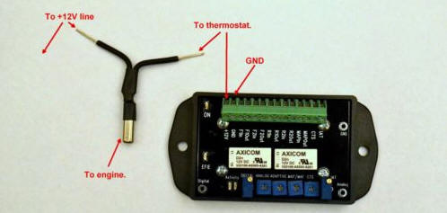
Temperature Sensor Wire
With the Tstat switching device, you will
need to solder on lengths of wire to the Tstat stub wires
in sufficient length to reach your 12 v ignition switched power source
and to reach the 12v input of your Tuning 101 Automated AFR Control
Center. Refer to above photo. Connect your terminal marked GND to either
the negative terminal of the battery or a GOOD clean chassis ground. |
|
|
|
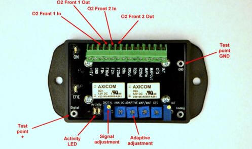 |
Upstream O2 Sensor Wires Determine your signal wire from each
02 sensor. This again will be identified in your repair manual wiring
diagram. We have also included in a separate document of instructions
for determining all of your signal wires with your volt meter as a
second alternative to your Haynes or Chilton's Service Manual diagram.
You will now cut the signal wire of your upstream 02 sensor above the
plug in block for the 02 sensor, anywhere between the plug in block and
the computer. What ever location is most accessible. You will need to
solder on a length of wire from the cut wire that goes directly to the
02 sensor and sufficient in length to reach your AFR Control mounting
location. This wire is attached to the connector marked F1 In. You will
now solder on a length of wire to the remaining portion of the cut
signal wire that goes to the computer and insert it into the connector
marked F1 Out. (partial instructions) |
| |
|
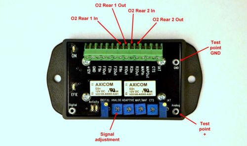 |
Downstream O2 Sensor Wires You will now be connecting your
downstream ( after the catalytic converter ) 02 sensors if your
vehicle has them. The procedure is the same as your upstream sensors.
Locate the signal wire of your First downstream sensor and cut it. You
will need to add lengths of wire to each side of your cut signal wire in
order to reach your AFR Control mounting location. The wire that goes
directly to the downstream 02 sensor is inserted into R1 In and the wire
that goes to the computer is inserted into R1 Out. If you have a second
downstream 02 sensor, once again locate the signal wire, cut it, and
sufficient wire
to each end of the cut signal wire to reach the mounting location of
your AFR Control. The wire that goes directly to the 02 sensor is
inserted into the connector marked R2 In, and the wire that goes to the
computer is inserted into the connector marked R2 Out. You are now
finished with the wiring for the EFIE portion of the AFR Control Center. |
| |
|
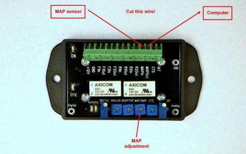 |
MAP/ MAF Sensor Wire The AFR Control Center contains a voltage
based MAF/MAP enhancer, which is prevalent in most vehicles today. There
are some vehicles that use a frequency based MAF sensor and a voltage
based MAP sensor. These are rare, and are usually found in some Ford &
GM products. If your vehicle has this combination, use which ever of the
two sensors is voltage based. You do not need to adjust the signals of
both. Either the MAF or the MAP will suffice.
If your vehicle has a voltage based MAF sensor we recommend using the
MAF |
| |
|
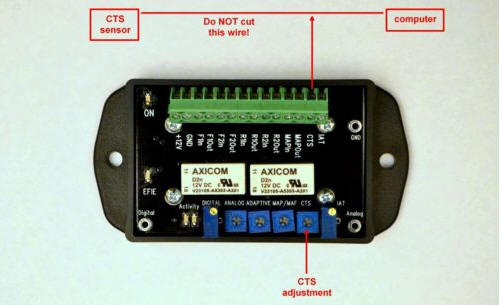 |
CTS Sensor Wire Locate your CTS. A word of caution: Some
vehicles have 2 almost identical CTS. (coolant temperature sensor’s) One
is for operation of a temperature gauge or indicator, and one that
supplies information to the ECU. Make certain that you locate and
connect to the one that is supplying information to the ECU. The one you
are looking for will have 2 wires, one will be a 5 volt input to the
sensor, and the other is your signal wire. |
| |
|
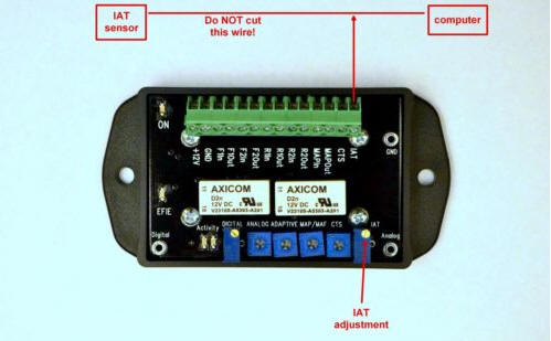 |
IAT Sensor Wire Locate your IAT ( intake air temperature )
sensor. There will be 2 wires going to the sensor. You will NOT be
cutting any wires. You will skin off some of the insulation from the
signal wire. Refer to your manuals diagram. Or you can refer to the
document Identifying your signal wires. Solder on a length of wire
sufficient in length to reach your AFR Control Center and attach it in
the terminal marked IAT. |
|
