 |
|
This is my best cell configuration. I am using 3
tubes inside the container. They are made of very low magnetic 304 stainless
steel.
-
1.5 inch cathode - 0.065 thickness
-
1.75 inch neutral - 0.065 thickness
-
2.0 inch positive - 0.065 thickness
-
4 inch container with a hole drilled in the bottom for the
cathode bolt. 0.083 thickness. A 3 inch container would work just as well.
-
Spacing between the tubes is 0.060 about 1/16th inch
|
|
 The tubes are held
together by spacers I made from a Poly cutting board. I cut the spacers
0.058 to 0.060 thickness. The tubes are held
together by spacers I made from a Poly cutting board. I cut the spacers
0.058 to 0.060 thickness. |
| |
|
 Turning the tubes on
end will make it easier to work with. Turning the tubes on
end will make it easier to work with.You are going to insert 3 spacers
about 120 degrees apart. Don't measure it, just eyeball it. |
| |
|
 You will need a pair
of needle nose pliers to squeeze the tubes closer together so as to make
room for the 3rd spacer. You will need a pair
of needle nose pliers to squeeze the tubes closer together so as to make
room for the 3rd spacer. |
| |
|
 Put 2 spacer in and
hold pressure on them so they don't drop down inside the tube. To get the
3rd spacer in, you will need to squeeze the tubes between those two spacers.
This provides just enough room for the 3rd spacer. If it is not a tight
fight, the tubes will slide out of place while you are driving down bumpy
roads. Put 2 spacer in and
hold pressure on them so they don't drop down inside the tube. To get the
3rd spacer in, you will need to squeeze the tubes between those two spacers.
This provides just enough room for the 3rd spacer. If it is not a tight
fight, the tubes will slide out of place while you are driving down bumpy
roads. |
| |
|
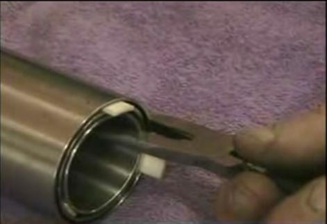
 You can see that it
makes a nice neat job if you align the insulators the same. You can see that it
makes a nice neat job if you align the insulators the same.Use a small
hammer to tap the insulators down even with the tube surface.
Notice the perforated flat plate that has been cut to fit and welded just
inside the tube. Flat plate would work. |
| |
|
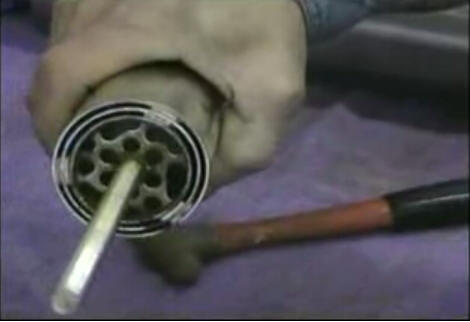
 It is very critical
for the tubes to be equally spaced apart, from top to bottom. Surfaces that
are closer will produce more HHO than surfaces farther apart. Take your time
and get this step right. It is very critical
for the tubes to be equally spaced apart, from top to bottom. Surfaces that
are closer will produce more HHO than surfaces farther apart. Take your time
and get this step right. |
| |
|
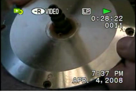
 Now that the tubes
are assembled to the cathode, it is time to insulate the cathode bolt from
the container. This particular container is a joecell setup. The bolt goes
out the bottom. You could easily use a solid bottom, and take the bolt out
the top of the cell - through the lid. More on that later. Now that the tubes
are assembled to the cathode, it is time to insulate the cathode bolt from
the container. This particular container is a joecell setup. The bolt goes
out the bottom. You could easily use a solid bottom, and take the bolt out
the top of the cell - through the lid. More on that later. |
| |
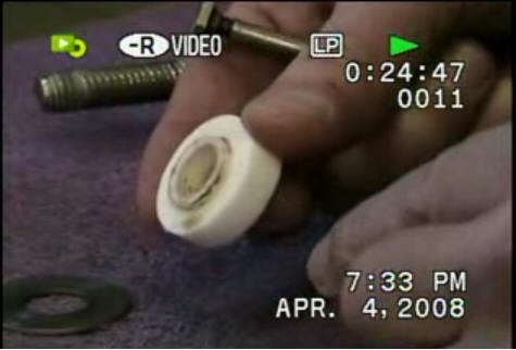
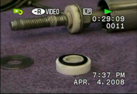 I made two
insulators out of cutting board material. The inside one is tightly threaded
onto the bolt to keep water from leaking between the threads. Notice the nut
and washer are used to keep the tubes off of the bottom. I made two
insulators out of cutting board material. The inside one is tightly threaded
onto the bolt to keep water from leaking between the threads. Notice the nut
and washer are used to keep the tubes off of the bottom.The lower
insulator is grooved for an O-ring |
| |
 Make sure the
insulators lip goes inside the hole. It keeps the bolt from touching the
container. Make sure the
insulators lip goes inside the hole. It keeps the bolt from touching the
container. |
| |
|
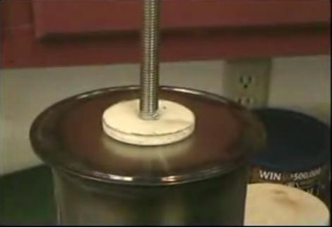
 Keep a firm grip on
the tube assembly as you tighten the nut. Don't let it slip. Take your time.
Keep the tubes straight up and down. Keep a firm grip on
the tube assembly as you tighten the nut. Don't let it slip. Take your time.
Keep the tubes straight up and down.We now have our cathode ready for the
Negative voltage. |
| |
|
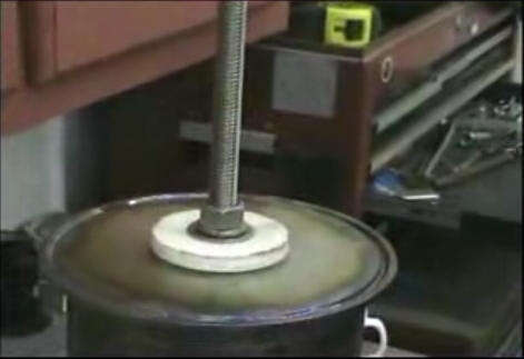
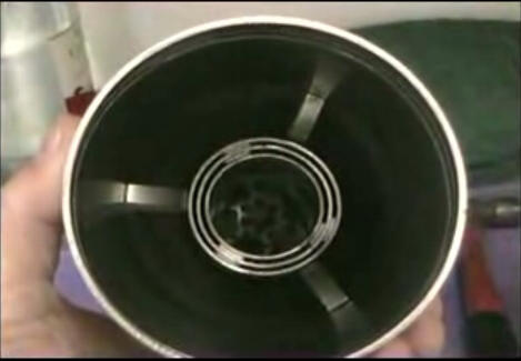
 The cell is ready
for a positive connector. Positive must be applied near the top of the outer
tube, the 2 inch-er. The cell is ready
for a positive connector. Positive must be applied near the top of the outer
tube, the 2 inch-er.You could weld or bolt a threaded rod to that tube
and take it out the side, or the lid.
I am doing something different.
|
| |
|
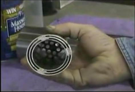
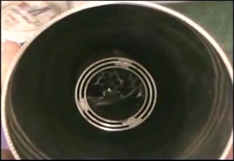
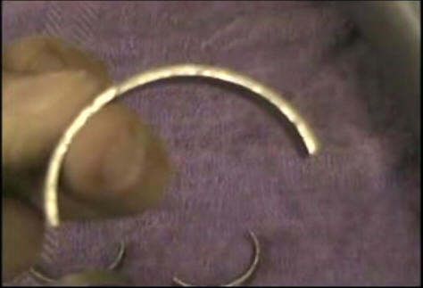 I plan to
experiment with the number of tubes. To make it convenient, I will make the
container positive and short it to the closest tube. I cut some wedges out
of a 2 inch tube. |
| |
|
 I bent the
wedges and forced them between the container wall and the tube wall. This
helps stabilize the top of the tubes. The connection needs to be very tight. I bent the
wedges and forced them between the container wall and the tube wall. This
helps stabilize the top of the tubes. The connection needs to be very tight. |
| |
|
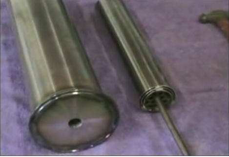
 The insulators have a
lip that fits into the hole in the bottom of the container. The insulators have a
lip that fits into the hole in the bottom of the container. |
| |
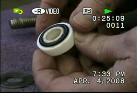 The lip needs to be a
little taller than the O-ring. The lip needs to be a
little taller than the O-ring. |

 This is the Lid.
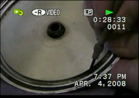 Bottom of the Lid.
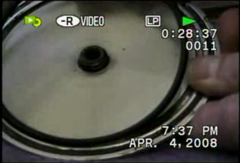 Installing the