|
| |
|
HHO Cell Configurator |
|
|
HHO Generators/Cells are being manufactured
by a lot of companies that only know what they see other companies
doing; they copy. They have no clue as to why the cell makes as little
or as much HHO as it does. All they know is it pumps out HHO when the
amps are increased. Most likely, you do not understand either. Not to
worry, I will explain it for you as we go.
But, before I get into the nitty gritty, I
should warn you; HHO companies make sales by boasting about Liter Per Minute
(LPM). They measure HHO with any kind of flow meter that will indicate
higher LPM; it makes their product look better. To my knowledge, no one,
using a flow meter, is measuring it accurate. Not even those that use Alicat Scientific Flow Meters, or Dwyer Hydroxy Flow Meters.
I take that back, Greenfuel H20 is using an Alicat correctly; he even
compares it with the water bottle test. It requires drying the gas
before it enters the meter. With this
in mind, I
came up with a method of predicting the HHO output of a cell --- before
you start the task of building it. The method is based on
operating voltage, amperage used, number of plates, size of plates, and
the number of cell stacks. My method is proven to be accurate when compared
to measurements taken by timing how long it takes to fill a 1 liter
bottle, and by greenfuelh2o's Alicat measurements. It works with Flat Plates and with Tubes. The plate arrangement
can be Unipolar, Bipolar, or a combination of both. My Configurator
is available to download Free, but first I think it would help you to
know more about how it works.
I searched the web extensively looking for
formulas that I could understand; formulas I could work with; there's
some complicated stuff out there. What I found, what I used, and the way
I used it came about by trial and error; lots of it. I did not get it
right, until I got the Cell Theory right. It was a learning
process that I am about to share with you; for Free.
The Configurator will help you understand
what variables affect HHO gas production. You will be able to size an
efficient cell capable of producing the LPM you desire, and know
ahead of time the amount of amperage needed to accomplish it. That means no more
guessing. That will save you both
time and money; and it is Free. My Serbian friend,
Milos Panic was kind enough to contribute to the cause by converting my
Microsoft Excel Configurator into an Executable Windows Program.
Calculations are made in both inches and
centimeters. Calculations can include actual dimensions of the assembled cell
(if you want to pursue it);
including the new Separation Cell design. Did I mention it is all Free?
The following bullets are key points of
my research and reasoning:
-
Faraday told us that 1.24 volts is the
minimum voltage for
electrolysis
efficiency.... that is, with the least amount of energy lost to heat. That is, 1.24 volts
of electrical pressure between 2 plates that make a water compartment. Higher voltage
results in increased heat energy. Yule Brown used
1.48 volts and Bob Boyce uses 2.0 to 3.0 volts. Through trial and error, I have
concluded that Faraday's 1.24 volts and Brown's 1.48 volts are impractical when using
straight DC as a power source; it is because of the amount of electrolyte needed
to lower the resistance of the water. 1.24 volts is very little
electrical pressure; it requires a lot of electrolyte. That is a big factor. Voltage is the prime
controller of heat and anything above 1.24 volts causes more of it. So if you
need 24 hour operating time, 7 days a week, you had best configure
for lower voltage across the plates. But wait; consider the
following:
I discovered that the
electrolyte determines the minimum voltage needed for electrolysis
to take place. Faraday's 1.24 volt minimum was based on the use of
Battery Acid. I discovered that NaOH minimum voltage is 1.69, and KOH minimum
voltage is 1.67. As it turns out, the electrolyte solution is
affected by
the voltage drop. Now I know why my 8, 9, 10, and 11 plate series cells
would not produce much amperage --- when using a 12 to 14 volt DC power
source.
-
Continuing on, we know that the cell plate voltage is obtained by dividing the
Operating Voltage" supply by the number of cells in Series with it (isolated water
compartments located between positive and negative electrodes). A
12 volt power source needs 10 water compartments in order to drop
the voltage to 1.2 volts per cell. That cell configuration looks like this + n n n
n n n n n n -.
That is an 11 plate series cell. HHO is produced in each of the 12 water
compartment at the rate of 10.44 MLPM for each ampere; says the late
great Michael Faraday.
-
Maximum Current Density: This is a biggie.
It is being miscalculated by everyone. Any electron flow
produces heat; any. Our goal is to minimize the heat. We know that each square inch of a plate surface, on one side
of a plate,
efficiently passes 0.54 amps of electrical current (Current Density).
For HHO purposes, we need to base our
calculation on the surface area between the gasket; inside the
gasket area. this is where amperage is going to flow from in order
to cross
the water. This is the area electron flow is going to be condensed
into using. This is where the plate is going to get the hottest. Higher amperage,
per square inch, increases HHO production, but also causes even more heat;
the more amperage, the more heat (along with more HHO).
There needs to be enough surface area inside the gasket area to handle the amperage you intend on
using. This is
a major factor in cell efficiency that is being overlooked or
exaggerated. This is what plate size is all about.
Plate size does
not increase HHO production, it establishes a maximum efficient
Current Density (maximum operating amperage). If enough surface area is not available to
handle the amperage passing across a plate, electron flow will pile up at
the nearest water crossing...and heat that area. Electrons need enough
room to move freely across the plate, without getting piled up; you
will find excess heat where they pile up. Examples: Have you ever
had a wire get too hot because its thickness was too small? Have you
ever noticed that a loose battery terminal gets hot?
(Physics defines Current Density as: The number of subatomic particles
per unit of time, crossing a unit area, in a designated plane,
perpendicular to the direction of movement of the particles). I
interpret that as "The number of Electrons, crossing an electrode
surface, perpendicular to the direction of travel".
-
We also know that the amount of HHO gas
produced is in direct proportion to the amount of power we use;
Volts x Amps = Watts of Power. Thus,
more surface area will increase the current density maximum (or
optimal) operating amperage we
are wanting to use.
Surface area can be increased by increasing the size of the plates,
but it does not increase gas production; number of plates
accomplishes that without increasing amperage in a series
arrangements of plates.
-
We also know that Hydrogen and Oxygen
are produced on opposing plates. This is a biggie. Faraday tells us
Hydrogen is equal to Amps x 0.000246 CFM, and Oxygen is equal to
Amps x 0.0001229 CFM. That gives us an HHO total of
0.0003689 CFM per
Water Cell area. It needs to be converted to Liters Per Minute, but that
figure we can work with.
-
That is my theory of understanding
efficient electrolysis of water.
So now we can use this information to configure an efficient Cell.
First, we need to measure the output voltage of our power source; in
most cases that
would be our Battery or Alternator. We needed this in order to determine the voltage between adjacent
plates (cell water area). Keep in mind, our vehicles have a 12 volt system, but the
Alternator produces higher voltages. It is that voltage that we must
account for.
-
If our vehicle's alternator is
supplying 13.5 volts, under a load, and we want to try and achieve 2
volts per cell, then we need to divide 13.5 volts by 2
volts in order to get the number of cells needed for electrolysis efficiency. If we figure
7, that will be close,
1.93 volts, 6 cells would be 2.25 volts per cell. In any case,
either figure is close enough.
-
Now add 1 to the number of cells and that is how many Plates
we
will need to build into the Hydrogen Generator Cell Stack.
To make this easier, use my
Configurator. I made it possible for
you to change the numbers; good for comparison, and good for
calculating your old cells. I can not tell you that the figures are perfect, but they are
close.
If your interest is just in the
Configurator, you can skip the next few paragraphs. But if you are new
to this technology, it may benefit you to read on.
The most efficient cell
configuration has one Positive plate and
one Negative plate,
with Neutral plates between them; that is a Series
Configuration. The same electrical current passes from the negative plate
(-)
to each neutral plate on its way to the positive plate. It
looks something like this ( - n n n n n n n n + ). The neutral plates
cause voltage drops between plates. It is that voltage drop that we need to
create.... for
efficiency. Simply counting all of the water spaces, regardless of the
number of positive and negative plates, will not cut it if there are
multiple positive and or negatives. If the voltage
drop in each cell (between positive and negative), does not add up to the value of the operating supply
voltage, then you are not doing correct measuring.
Series Parallel cells have multiple
Series cell stacks in Parallel; sharing positives and or negatives ( - n n n + n n n - ). A Series Parallel
Cell is actually 2 Series cells ( - n n n +) and (+ n n n - ). They
can not be
calculated as 1 cell. The reason is, they are 2
cells (stacks). The cell voltage is cut in
half, every time a neutral is added between + and -. No neutrals means full battery
voltage or alternator voltage. One neutral cuts that in half. Two
neutrals cuts it in half again; etc. etc. etc. My Configurator
calculates these as Stacks.
Parallel: If your cell has alternating positive and negative plates, you will
never achieve operating efficiency
(+ - + - + - + - ). You will always have operating voltage
supplied to each cell. That is about as Brute as you can get. It will
make a lot of gas and it will make a lot of heat.... unless you add enough
stacks to lower the amp flow..... through each stack (a stack is a set
of + & - plates. Adding more sets will
prolong the inevitable heat buildup. In addition, the amperage will eat up the
positive plates faster than any other configuration.
Have you ever seen a Wire cell? Hello !
They make good water heaters. You pour the amperage to them in order to
get them to make gas. It does not take long for them to heat up and
deteriorate. What Wire cells do best is create water vapor. It is that
water vapor that is providing most of the fuel efficiency increase
results. It
has to be. Wire cells just do not make enough HHO to account for the
benefit they provide. (ok Ozie, your secret is out).
Conclusion
So, now we have come full circle. As
experimenters, we
started out with Brute Force alternating positive and negative plates.
Then we figured out that a series of Neutral plates lowered the heat and
produced more gas. Then we figured out how to combine two series cells
into one bigger cell, and how to maximize the efficiency and produce more
gas with less heat. All along the way, the ratio of gas increased while the
water vapor decreased. We did this because the experts warned us to keep
the water vapor out of the engine. It is bad for the engine. It will
rust the engine. It will rust the injectors. Blah Blah Blah. Hog wash.
Your engine was designed to handle the vapor. Hydrocarbon fuels are made
up of Hydrogen and Carbon (mostly). When Hydrogen mixes with Oxygen in
the combustion chamber ..... the by product is Water. Did you catch
that? Burning Gasoline and Diesel produces a by-product of water - in
the combustion chambers.
In closing, I offer one
suggestion. If you want to make HHO and or water vapor, start with a
safe container; one that can take the Heat. Have fun with the
Configurator. If you need help with it, click on HELP at the top of this
page. If you have comments or suggestion, please let me know by way of
my Help page. |
|
| |
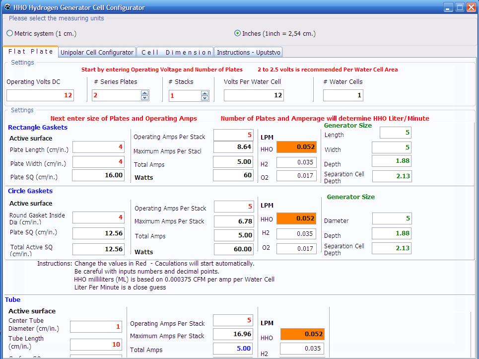
 Configurator
- Version March 7, as a Windows Program. (HHOCalculator.exe) Configurator
- Version March 7, as a Windows Program. (HHOCalculator.exe)
Click to Download the Configurator. If your Anti-Virus
Protection stops you, please Allow.
Add the Icon to your Windows Desktop. The program is virus free if it
comes from me. It is Free to use.
This program is Open Source information; not to be sold.
 |
|
 Configurator
Instructions
Configurator
Instructions
|
|
My Serbian
friend, Milos Panic was kind enough to
contribute to the cause by converting my Microsoft Excel Configurator
to an Executable Program. He did not include "Credits" when
building the Configurator, so I am doing so here.
Thank you Milos. We appreciate your many hours of hard work, that turned
into days and weeks. Here is a screenshot of my Open Source Hydrogen Generator Cell
Configurator:
|
|
 |
|
|
|
Reference to MMW information that provides this
data.
Understanding Amperage
|
Notes:
- I have some concerns about the plate square inches vs. their
maximum amperage. The current is passing thru the cell area, from
one plate to another, to another. The gases being produced on the
plate surfaces are being calculated as a total; both hydrogen and
oxygen. The hydrogen is equal to the Amps x .000246. The oxygen is
equal to Amps x .0001229. These numbers are CFM (cubic feet per
minute). They must be multiplied by 28.3 to get Liters.
- Optimal Amps - anything more than the optimal current density, causes or
results in - wasted energy in the form of heat. One can accomplish
the same LPM output, using fewer plates...and higher amperage... but the cost will be excess
heat. It is this heat that causes your amperage to gradually increase.
I built an 11 plate series cell and tested it. It had 1.25 volts per
cell, and was rated at 3 amps, based on the plate surface area. I
could not get the amperage to go more than 3.5 amp, no matter how
much electrolyte; it ran cool for 8 hours. I reconfigured for 7
plates, 2.25 volts per cell, at 13.5 volts from the alternator, I
used the same electrolyte mix and got 10.5 amps and 3 times the gas.
- 7 plates seems to be the best hho producer, with the best
efficiency, when using 12 to 15 volts DC. Tests with 8 or more
plates increases the resistance of the water so much that very large
amounts of electrolyte are needed to get electrolysis started.
- The purpose of the calculator is to establish the number of
plates needed for a particular operating voltage, and to establish
the operating amperage for the square inch surface area of
those plates. I think this will help experimenters understand what
efficiency is ... and how to build around it.
- Several languages will be added; English - Inches, English -
Centimeters, German, Russian, Serbian, Spanish, Chinese. Others may
follow.
- The configurator now calculates the size and depth of Separation
Cells. It provides the number of additional gaskets that will be
needed. Basically, it is one more per water area; and of course your
membranes.
- Feb. 10th, added Tube Cells to the configurator. Once I
understood the relationship between Amperage and Number of Water
Cells, Tubes were easy to configure. It was a learning process.
Number of Plates :
References the difference in efficiency comparing cells with 2, 3, 4, 5,
6, and 7 plates in Series. A chart shows the required amperage needed to
produce 1 LPM of HHO -- for each cell plate configuration. It also shows
the plate voltage, and Current Density needed for Continuous operation. |
|
|
Feedback |
|
|
I have done many tests
with one liter and half liter bottles at different amp setting and
compared the results with your HHO
calculator. I can say for sure that your
calculator is absolutely correct.
Leon@geshho.com
|
|
|
|
|
Mileage Seekers HHO
http://mileageseekershho.webs.com/apps/forums/topics/show/728735
The Chemistry and Manufacture of
Hydrogen
Download or Read On-Line
by P. Litherland Teed
Page 131
It has been deduced from Faraday’s
laws that one ampere of current for one hour should produce .0147 cubic
feet of hydrogen. (Paraphrased from “The Chemistry and Manufacture of
HYDROGEN” by P. Litherland Teed page 131 – LONDON Edward Arnold 1919)
this book being obtained from www.knowledgepublications.com.
This equates to; amps X .000245 = CFM hydrogen. The equation I received
from an electrochemical engineer I’m acquainted with is; amps X .000246
= CFM hydrogen, and amps X .0001229 = CFM oxygen. The accepted unit of
measure of gas output that we use for the HHO cells we work with is LPM
(liters per minute). To convert our calculated CFM of gas to LPM we
multiply by 28.3.
For an example; assume a cell of
one anode and one cathode (one gap between them) operating at 12 volts
and consuming 12 amperes. Generated hydrogen would be 12amps X .000246 =
.002952 CFM, generated oxygen would be 12amps X .0001229 = .0014748 CFM.
Add the two together and multiply by 28.3 and we have .1253 LPM or
125.3ml/min HHO. We see that this cell doesn’t produce much HHO and
being the plate to plate voltage is 12 we know we have a really good hot
water heater.
Practical experience tells us that
plate to plate voltage should not be much over 2 to minimize heat gain.
To achieve this in our test cell we must add 5 bi-polar (or commonly
referred to as neutral) plates for a total of 7 plates having 6 gaps
between them. The voltage is now reduced between each plate to 2, 12
volts divided by 6 gaps; however the current remains at 12 amps between
each plate. Having 6 gaps at 12 amps each we now plug 72 into our
equations; (72 X .000246 = .017712 + 72 X .0001229 = .0088488 = .0265608
X 28.3 = .7516 LPM) three quarters of a liter at 12 amps, not bad and
very little heat gain. We can increase our gas volume, along with
current consumption, without additional heat gain, by connecting two or
more of our seven plate cells electrically in parallel.
When I first came upon these
equations I wondered how close they were to the real world. Through
empirical testing on the calibrated flow bench, of several different
cells, I found that these equations are accurate. Some cells getting
closer to calculated output than others, none getting more, due most
likely to efficiencies of design.
There are many parameters involved
when designing a cell; gas quantity desired, sustained current
available, and space required for mounting are primary concerns. We now
see how we can calculate gas volume using available current. When
designing for space requirements we need to consider how much current
will be passing each plate. Heat generation results from a combination
of voltage and current. We have seen that voltage can be controlled by
the number of plates we use in each cell. We can control current via
external means by using a pulse width modulator; there are some very
good ones available. However, in the design process of our cell, by
juggling the amount of parallel cells, the current to be used and the
size of the plates, we are able to get a pretty good handle on the heat
gain we will experience. An important consideration is current density
on each plate in the cell. A good rule of thumb is to try to achieve a
current density of .5 amps per square inch or less.
In our test example above running
at 12 amps, in order to achieve our .5 amps /sq. inch, since we have 12
amps flowing through each plate, we’ll need plates equaling 24 sq. inch
each. Possibly 3 X 8 inches or maybe 4 X 6 inches. If we have room and
can make the plates larger, all the better, it will lower the current
density and or allow for the use of more current thus producing more
gas.
As we have seen, we are able to
closely calculate the expected HHO output of cell designs, albeit there
are many factors to consider when starting with a clean sheet of paper.
Physics defines Current Density.
The number of subatomic particles per unit time crossing a unit area in
a designated plane perpendicular to the direction of movement of the
particles.
|
|
|
Faraday's laws for electrolysis are:
First Law :
The quantity of a substance produced by electrolysis is
proportional to the quantity of electricity used.
Second Law :
For a given quantity of electricity the quantity of substance
produced is proportional to its weight.
The magic numbers:
Faraday's number is 96,484 Coulombs/mol (often rounded to 96,500.) (see
http://www.ausetute.com.au/faradayl.html )
One liter of hydrogen weighs 0.08988 grams/liter, so 1 liter of hydrogen
is 0.08988 moles. (see http://en.wikipedia .org/wiki/
Hydrogen)
Faraday's laws can be summarized by
m \ = \ \left({ Q \over F }\right)\left( { M \over z }\right)
where
/m/ is the mass of the substance altered at an electrode
/Q/ is the total electric charge passed through the substance
/F/ = 96 485 C mol^-1 is the Faraday constant
<http://en.wikipedia .org/wiki/
Faraday_constant>
/M/ is the molar mass of the substance
/z/ is the valence number of ions <http://en.wikipedia .org/wiki/
Ion>
of the substance (electrons transferred per ion) (see
http://en.wikipedia .org/wiki/
Faraday%27s_ law_of_electroly sis)
Solving for "Q" we get Q=m*F*z/M Hydrogen has a valence of one and a
mass of one, let's put in the numbers:
Q=0.08988 * 96484 * 1 = 8672 (roughly) coulombs per liter of hydrogen.
Since Amperes are Coulombs/second, 1 LPM needs 144 Amperes FOR A SINGLE
CELL. For a series cell, this is divided by the number of cells, so for
a 6 cell system (7 plates), we should need about 24 Amperes. However,
when we produce hydroxy (or whatever name you wish to use), we also
produce 1/2 mol of oxygen per mol of hydrogen.
So, for each mol (gram) of Hydrogen, we produce 1/2 mol (6 grams) of
oxygen. Oxygen has a density of 1.429 g/L, so 4 Liters of Oxygen for
each 11 liters of Hydrogen or 15 Liters of hydroxy, so we really only
need 144 *11/15 or 105.6 Amperes or 17.6 Amperes per liter per minute
for a 6 cell system.
Voltage (and power) do not appear in Faraday's equation as far as I can
tell. However efficiency can be derived from the potential at which
electrolysis starts (1.24 Volts, IIRC) and the current per liter per
minute (105.6 Amperes) givng us 1,000 mL/minute/(105. 6*1.24) or about
7.64 M/M/W. When higher values are claimed, either there is water vapor
in the gas, the temperature correction has not been applied, or
something else is odd. Claims of higher than 7.64 MMW should be
examined for possible error. |
|
Hydrogen Generator Configurator Calculator
hho plate configurator hho cell configurator dry cell
configurator |
Page Last Edited -
04/11/2022
|
