"If it has a Fan on it --- it
could be over rated"
Do you really need a PWM? Not really,
But without them, the HHO experimenter will be
busy observing and maintaining the amperage flow of the HHO electrolyze.
And, it is nice to be
able to control the output of your hydrogen generator - from your dashboard.
During winter months, we need more electrolyte in the water because cold
water does not conduct electricity as well. In summer months, we need less
electrolyte in the water because hot water conducts electricity much better
than cold water. During periods of mixed hot and cold, you are screwed; unless you
have a PWM. The PWM allows you to use more electrolyte, but still control the output of the HHO generator.
The purpose of the PWM is to pulse the DC voltage to the
cell. Pulsing the voltage turns the current on off on off on off, thus
reducing the heat caused by constant current flow. In other words, just as
the current starts to flow, it gets stopped. The series of starts and stops
happen instantaneously.
In addition, the PWM allows you to regulate the amperage
(current). This provides runaway control over the cell. The longer the cell
runs on DC, the hotter the water will get, the higher the amps will go.
Eventually you will blow a fuse, pop a breaker. The PWM solves that problem.
Some PWM's are self regulating (CC); meaning, they are made to
operate at a Constant Current, even as the water gets hotter. You set the
maximum output, and forget it.
It is also believed that PWM's help
make a higher quality of the HHO. They do so by increasing the % of Ortho-hydrogen
and decreasing the % of Para-hydrogen. Ortho-hydrogen is about 3 times
more powerful than Para-hydrogen. Ortho-hydrogen is what causes the Pop or
loud Snap sound that hurts your ears when HHO bubbles are ignited.
Straight DC amperage normally produces 75% Ortho-hydrogen and 25%
Para-hydrogen. I am investigating this and will post future information.
Please be advised: A PWM will not increase your HHO output. It will do just the opposite. It will
slightly lessen the
output; based on what you set it to produce.
PWM Features to look for:
Maximum Continuous Amperage Output, not Maximum
Amperage. This is the maximum amperage the PWM can be operated at,
constantly; long periods, not short operating periods.
Automatic Current Limiting, Constant Current
(CC). This allows you to set the Amperage Output to a specific amperage.
The PWM then will maintain that amperage, regardless of the water
temperature.
Adjustable Pulse Frequency. This allows you to
adjust the time between pulses. Fast pulsing causes more heat than slow
pulsing. Pulsing turns the cell on and off rapidly; as rapid as you set
the frequency.
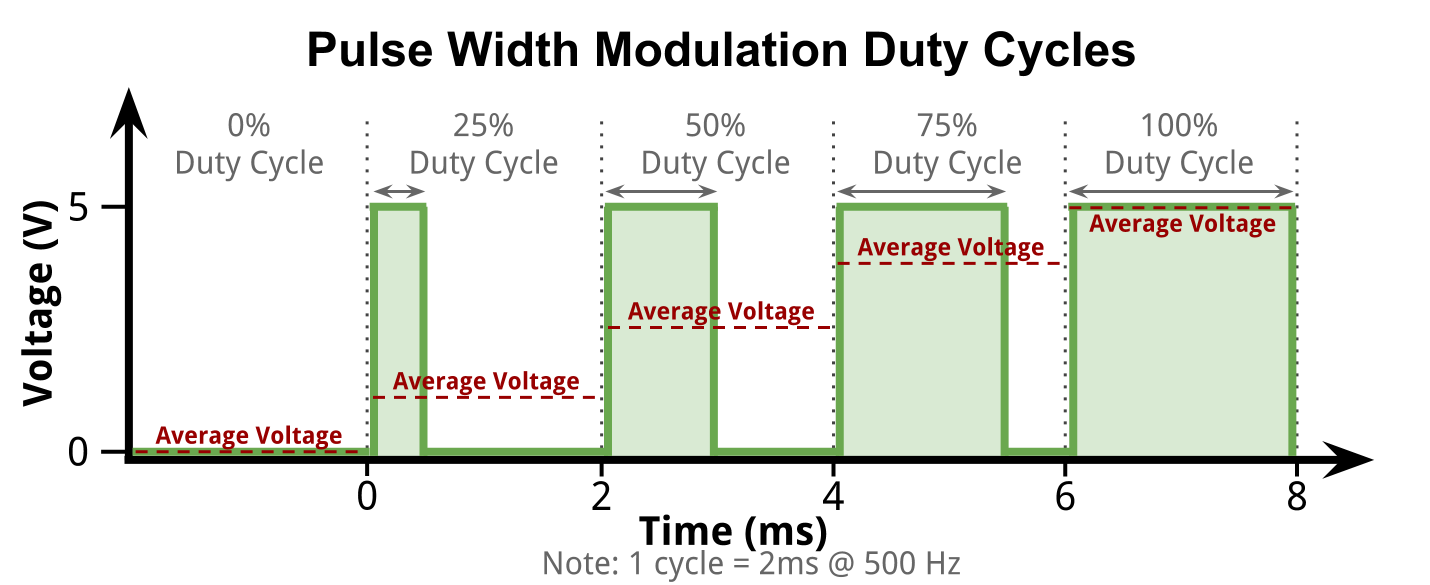
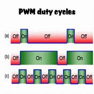
Duty Cycle Adjustment. The duty
cycle reading lets you know if your electrolyte fluids are too weak or
too strong as the duty cycle of an automatic current limited PWM will be
approximately 70% when the Cell is warmed up (depending on your Cell
design). If it is significantly higher, you know you have too little
electrolyte and if it’s significantly lower, you have too much
electrolyte. If the Cell is cold, the current should be at or very close
to the set limit (duty cycle will be approximately 100%).
Advanced PWM Features to look for:
Alternator Protection. Guards against
situations that could over work your alternator and cause it to fail.
One side effect of automatic current limited PWM’s is that they give the
Cell current high priority over every other circuit on your vehicle. To
understand this better you need to understand how your electrical system
works. If the system voltage drops, every device in your vehicle gets
less current because their DC resistance is fixed; this is by design.
Lower the voltage across a fixed resistance and less current flows
through it; but attach a big load to a automatic current limited PWM and
the current going through it will remain fixed as a lower voltage will
cause the PWM to increase its duty cycle to maintain the fixed current.
The alternators output capability depends on two things, the speed in
which it is being driven and by the field current being fed to it
through the voltage regulator. The voltage regulator maintains a voltage
around 14v, give or take a few tenths of a volt. When the system voltage
falls below the regulated voltage, the regulator feeds more current to
the field coils of the alternator to get it to produce more current. The
higher current in the field coils adds a higher mechanical load to it
which slows down the engine. Alternator Protection dials back the duty
cycle regardless of what the current limit is set to until the current
is again available (when you accelerate). It gives your Cell current the
lowest priority in the system; which is exactly what should be done.
After all, you really don’t need much output when you are idling. So the
alternator protection not only prevents your alternator from failing due
to overload, but it also helps maintain a smooth idle and prevents you
from unnecessarily having to increase your idle. One might think that
having the throttle or engine speed control the duty cycle would yield
the most optimum results, but it will actually have a negative effect.
The reason is due to generator latency. Hydroxy gas is mostly needed
when you accelerate and since it takes at least a few seconds for
pressure to build after current is increased, there would be a
deficiency of gas produced at the time when your engine needs it the
most which will negatively affect your results.
Charge Sensing Switch. Thisis what
automatically turns the cell on and off. When charge voltage greater
than approximately 13.8v is sensed, power is turned on and stays on
until the charge voltage drops below approximately 13.2v (when
alternator stops generating current). This means that the PWM will only
turn on when your alternator is supplying the current. I makes it
impossible to leave the cell on, if the engine is not running. You are
not required to wire into the ignition circuit.
Short Circuit Protection. Thisis not generic
like a fuse; it is specially optimized for a Cell. Fuses are designed to
open from the heat generated by the short circuit. They need to be
flexible enough to work with motors and other inductive loads which
generate current spikes that would open the fuse if this was not so; the
same is true with generic circuit breakers. Fuses can take up to 100
milliseconds to open after exceeding their rated amperage; that’s a
tenth of a second. It may be quick enough for a motor winding, but not
for a semiconductor. A typical PWM relying on fuse protection may
survive several times after a short circuit, but the heat that the fuse
sees is also the heat that the MOSFET’s see. This means that every time
a fuse pops, there is at least some damage happening to the MOSFET’s due
to the current spike in a typical PWM.
Over Current Protection: prevents you from
dialing in currents significantly higher than thePWM recommends.
Disable Terminal: allows you to hook up as many
turn off devices as your application requires. These devices are
essential to bullet‐proof your system. Any connection to chassis ground
will disable the PWM output. You may use this for safetydevices, such as
temperature, water level, pressure switches on your Cell and/or just a
simple toggle switch for when you don’t want your Cell to operate.
When you purchase a PWM, pay
close attention to the output rating. Most sellers do not tell you the
"Continuous" Output. If they say it is a 30 amp PWM, in most cases that is a
Peak or Maximum output rating. You can not operate at maximum very long. If
you want or need a constant 30 amp output - make sure the PWM you purchase
can withstand that output continuously. It is better to have too much PWM,
than not enough; the output is adjustable.
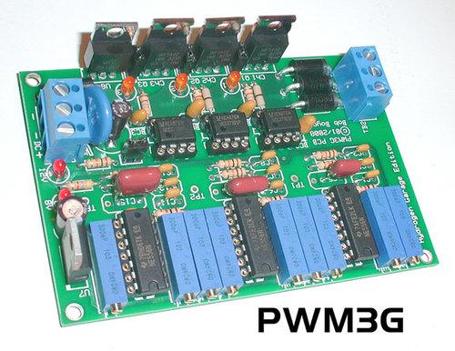
Built in Display for Amps, Duty cycle and Frequency
Adjustable Frequency, 300hz to over 3khz
Disable Terminal (Optionally attach toggle, water pressure,
water temperature, water level switches to your car to disable
your cell on a fault condition)
Easy three wire installation
No Power Relay needed
Go-no-Go switch is built-in
to start and stop the HHO electrolyzer when the engine is
operating or not operating.
This PWM is no longer available
Smart PWM - 40 amps Continuous Output
Automatic On/Off voltage sensing capability
Constant Current Adjustment
Frequency Adjustment
Low/High Voltage Setting
Error Codes
Water Level Indicator capability
FuelSaver-MPG.com
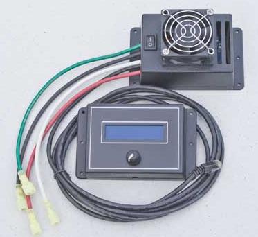
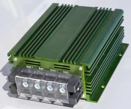
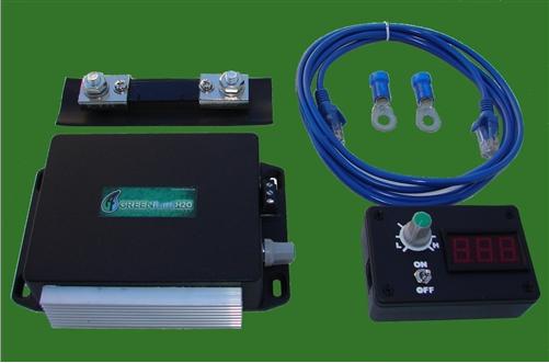
100 Amp Smart PWM
This item
comes complete with everything you need to run the PWM. It includes
the PWM, the Liquid Crystal Display/Contrller and a 25' cat5 cable to
connect the controller to the PWM.
FuelSaver-MPG.com
40 Amp CC PWM
Hydrogen Boost Now
Constant Current PWM,
and Remote
( Experimenters are Reviewing this PWM's reliability)
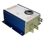
Continuous 50, 70, 90 Amp Models (not recommended for under 10 amps)
12 to 48 vdc
Frequency = 500 HZ
Remote for on/off, amperage adjust, and built-in amp gauge
No Fan, and 50 A model does not have a heat sink.
Heavy Duty Electronics
Constant Current only maintains +/- 10% (not so good)
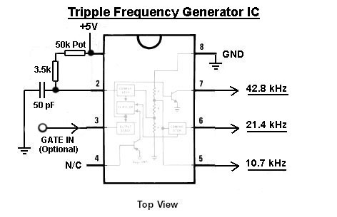
A pulsed
square wave DC circuit, with 3 frequency adjustments & 3 wave length
adjustments. To be used with electrolysis, to break the 1825 Faraday's law
of electrolysis; up to 4x's with a ortho spin state of H and O.
Information
available at Hydrogen Garage
PWM - Cell Mounting Hardware
Any time you use a PWM to power your Cells, you are going to have to keep
the PWM negative ground from touching the vehicle frame or chassis (which is
grounded to the battery). If they touch, the PWM will not Pulse the DC
voltage. The PWM ground must be isolated. A good way to keep them from
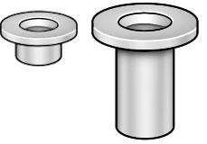
touching is to use Nylon Shoulder Washers.
Nylon Shoulder Washers
Use these to insulate your Cell and mounting bolts from touching the
chassis or frame ground. It may be necessary to use 2; 1 top and 1 bottom of
each bolt.
The Cell electrodes must not touch the frame ground.

 The purpose of the PWM is to pulse the DC voltage to the
cell. Pulsing the voltage turns the current on off on off on off, thus
reducing the heat caused by constant current flow. In other words, just as
the current starts to flow, it gets stopped. The series of starts and stops
happen instantaneously.
The purpose of the PWM is to pulse the DC voltage to the
cell. Pulsing the voltage turns the current on off on off on off, thus
reducing the heat caused by constant current flow. In other words, just as
the current starts to flow, it gets stopped. The series of starts and stops
happen instantaneously.